According to abbreviationfinder, IDE stands for Integrated device Electronics and ATA stands for Advanced Technology Attachment which controls mass data storage devices such as hard drives and ATAPI(Advanced Technology Attachment Packet Interface) and also adds devices such as CD-ROM drives.
History
In the IDE system the device driver is integrated into the device electronics. The various versions of ATA systems are:
- Parallel ATA (PATA acronym in use)
- ATA-1.
- ATA-2, supports fast block transfers and multiword DMA.
- ATA-3, is the revised and improved ATA-2. All of the above support speeds of 16MB / s.
- ATA-4, known as Ultra-DMA or ATA-33, which supports transfers at 33 MB / s.
- ATA-5 or Ultra ATA / 66, originally proposed by Quantum for 66 MB / s transfers.
- ATA-6 or Ultra ATA / 100, support for 100MB / s speeds.
- ATA-7 or Ultra ATA / 133, support for 133MB / s speeds.
- ATA-8 or Ultra ATA / 166, support for 166MB / s speeds.
- Serial ATA, remodeling of ATA with new connectors (power and data), cables, supply voltage and commonly known as SATA, supports speeds of 150 MB / s (SATA), 300 MB / s (SATA II) and 600 MB / s (SATA III).
Ata over ethernet implementation over Ethernet of ATA commands to mount a SAN network. Presented as an alternative to iSCSI
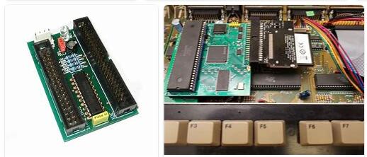
At first, IDE controllers were used as expansion cards, mostly ISA, and were only integrated into the motherboard of brand-name computers such as IBM, Dell or Commodore. Its most widespread version were the multi I / O cards, which grouped the IDE and floppy controllers, as well as the RS-232 ports and the parallel port, and only high-end models incorporated SIMM sockets and connectors to cache the disk. Device integration meant that a single chip was capable of doing all the work.
With the advent of the PCI bus, IDE controllers are almost always included on the motherboard, initially as a chip, to become part of the chipset. It is usually presented as two connectors for two devices each. Of the two hard drives, one has to be as a slave and the other as a master so that the controller knows to / from which device to send / receive the data. The configuration is done via jumpers. Typically, a hard drive can be configured in one of three ways:
As a Master (‘Master’). If it’s the only device on the cable, you should have this setup, although it sometimes works as a slave as well. If there is another device, the other must be slave.
Like Slave (‘slave’). There must be another device that is master. Cable select (cable select). The device will be master or slave depending on its position on the cable. If there is another device, it must also be configured as cable select. If the device is the only device on the cable, it must be in the master position. Different colors are used to distinguish the connector into which the first Ide bus will be connected (Ide 1).
This design (two devices on one bus) has the drawback that while one device is being accessed the other device on the same IDE connector cannot be used. On some chipsets (Intel FX triton) you couldn’t even use the other IDE at the same time.
This problem is solved in S-ATA and SCSI, which can use two devices per channel.
IDE disks are much more popular than SCSI disks due to their much lower price. IDE performance is lower than SCSI, but the differences are narrowing. The UDMA does the function of the Bus Mastering in SCSI which reduces the load on the CPU and increases the speed and the Serial ATA allows each hard disk to work without interfering with the others.
Anyway, although SCSI is superior, the S-ATA alternative is being considered for high-end computer systems since its performance is not much lower and its price difference is more advantageous.
Specs
Hot-pluggable no External no Width 16 bits Bandwidth 16 MB / s originally After 33, 66, 100, 133 and 166 MB / s Max no. Devices 2 (master / slave) Parallel Protocol Cable 40-wire flat ribbon cable, later increased to 80 for security. Pins 40 Pinout Pin 1 Reset Pin 2 Ground Pin 3 Data 7 Pin 4 Data 8 Pin 5 Data 6 Pin 6 Data 9 Pin 7 Data 5 Pin 8 Data 10 Pin 9 Data 4 Pin 10 Data 11 Pin 11 Data 3 Pin 12 Data 12 Pin 13 Data 2 Pin 14 Data 13 Pin 15 Data 1 Pin 16 Data 14 Pin 17 Data 0 Pin 18 Data 15 Pin 19 Ground Pin 20 Key or VCC_in Pin 21 DDRQ Pin 22 Ground Pin 23 I / O write Pin 24 Ground Pin 25 I / O read Pin 26 Ground Pin 27 IOC HRDY Pin 28 Cable select Pin 29 DDACK Pin 30 Ground Pin 31 IRQ